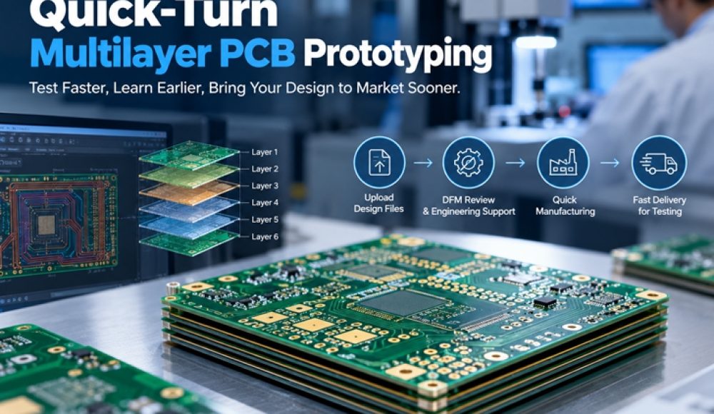
Quick-Turn Multilayer PCB Prototyping: Test Faster, Learn Earlier
In electronics development, the value of a PCB prototype is not measured only by how quickly a manufacturer ships it. The real value comes from how soon engineers can test critical assumptions, identify design problems, and make informed decisions about the next revision.
This is particularly important for multilayer PCB projects involving industrial controllers, communication equipment, embedded computing, and intelligent electronic devices.
A six-layer or eight-layer PCB may contain several interacting systems, including high-speed signals, power distribution networks, processors, and sensitive analog circuits. Even when simulation results are promising, physical validation remains essential.
Quick-Turn Multilayer PCB Prototyping helps OEM engineering teams shorten the interval between design decisions and measurable results.
However, rapid fabrication is most useful when the prototype order is organized around clear technical objectives.

Why Faster Prototypes Create More Engineering Value
Traditional product development often treats PCB fabrication as a separate purchasing activity.
Engineers finish a design, send files to a supplier, wait for delivery, and begin testing only after the boards arrive.
If the prototype reveals a problem, the entire cycle repeats.
A faster manufacturing cycle can allow more time for electrical validation, firmware development, environmental evaluation, and design refinement.
For example, an industrial controller team may need to verify communication stability before committing to enclosure tooling.
A networking equipment developer may need to evaluate signal quality under realistic operating conditions.
In both situations, receiving usable prototypes earlier can accelerate engineering decisions.
The objective is not simply faster delivery; it is faster learning.
Define the Questions Each Prototype Must Answer
Before ordering multilayer PCB prototypes, engineers should identify the specific uncertainties they want to resolve.
Typical questions include whether the power distribution system operates within its limits, whether high-speed interfaces meet performance targets, and whether the mechanical assembly fits correctly.
Other projects may focus on thermal behavior, connector placement, or compatibility with existing equipment.
These questions determine the required prototype configuration.
For example, a board intended for signal-integrity testing should preserve the approved stackup and critical transmission-line structures.
A prototype intended for mechanical verification may emphasize board dimensions and mounting features.
Clear objectives help prevent unnecessary fabrication requirements while protecting the characteristics that matter.
Select the Right Prototype Quantity
There is no universal quantity for a PCB prototype order.
A few boards may be sufficient for initial electrical evaluation.
Additional boards may be needed when several engineers are testing different functions simultaneously.
Environmental testing, destructive analysis, or assembly process evaluation may require more samples.
OEMs should therefore determine prototype quantities based on the validation plan rather than an arbitrary minimum order.
For example, a team might allocate boards to firmware development, electrical testing, mechanical integration, and spare units.
This approach makes prototype purchasing more purposeful.
It also helps manufacturers understand why the requested quantity may be small but technically important.
Keep Critical Multilayer Requirements Consistent
Quick-turn PCB manufacturing should not introduce uncontrolled changes to the features being evaluated.
If the final product requires controlled impedance, the prototype must reflect the relevant electrical requirements.
Similarly, changes in laminate properties, dielectric thickness, copper geometry, or via construction may affect test results.
For high-speed or RF applications, these differences can be significant.
Therefore, engineers should identify which specifications are essential to prototype validity.
The manufacturer can then review whether those requirements are achievable within the requested schedule.
When a proposed manufacturing adjustment affects a critical characteristic, customer approval should be obtained before fabrication.
A fast prototype is only valuable when its results are relevant to the intended product.
Organize Engineering Files for Immediate Review
A complete fabrication package reduces the number of questions that must be resolved before production.
Typical files include Gerber or ODB++ data, NC drill files, fabrication drawings, and stackup specifications.
Controlled-impedance requirements, material preferences, copper thickness, and surface finish should also be identified.
File revisions must be consistent.
For example, sending updated Gerber files with an outdated drill file can create uncertainty about the approved design.
A concise manufacturing note can highlight unusual requirements and important tolerances.
The objective is to make the project easy to evaluate without sacrificing technical accuracy.
Use Parallel Engineering Activities
Quick-turn PCB fabrication can create additional value when other development activities continue simultaneously.
While bare boards are being manufactured, the engineering team may prepare firmware, test software, assembly instructions, and measurement procedures.
For projects requiring PCBA, component sourcing can also begin after the BOM and purchasing requirements are approved.
This coordination reduces idle time after PCB delivery.
However, parallel work must be based on controlled revisions.
If the design changes, the team should evaluate whether associated programming, fixtures, or assembly data also require updates.
Effective scheduling depends on coordination, not simply overlapping every activity.
Evaluate Prototype Results Systematically
Prototype testing should produce documented engineering evidence.
For example, engineers may record voltage stability, signal quality, operating temperature, interface performance, and observed defects.
Test conditions should be consistent enough to support meaningful comparisons between revisions.
If a failure occurs, the team should determine whether it originated from the circuit design, manufacturing variation, component assembly, or test setup.
This distinction is essential.
Changing a PCB layout to correct an assembly defect may introduce unnecessary redesign work.
Likewise, accepting a prototype without investigating an intermittent failure may create larger problems later.
Use Revision Comparison to Accelerate Decisions
When several PCB revisions are required, a structured comparison process helps engineers understand whether changes produced the intended results.
Each revision should have a unique identifier.
The team should record what changed, why it changed, and which tests were repeated.
For example, one revision may modify power distribution while another adjusts a communication interface.
Keeping these changes traceable helps prevent confusion during troubleshooting.
It also makes it easier to transfer validated requirements into future manufacturing orders.
Fast iteration is most effective when engineering knowledge is preserved between builds.
Understand What Quick-Turn Manufacturing Cannot Guarantee
Quick-turn capability does not mean every multilayer PCB can be manufactured within the same timeframe.
Specialized laminates, complex via structures, unusual board thicknesses, and demanding inspection requirements may introduce additional constraints.
A manufacturer must evaluate the actual design before confirming feasibility.
Similarly, PCB fabrication speed should not be confused with the complete turnaround time for assembled and tested PCBAs.
Component availability, programming, and functional testing can affect the overall schedule.
OEMs should therefore request a realistic quotation based on their complete project requirements.
Quick-Turn PCB Manufacturing Support From Ring PCB
Effective rapid prototyping combines engineering readiness, controlled fabrication, and clear communication.
Ring PCB supports OEM projects with multilayer PCB manufacturing, PCB prototype fabrication, engineering DFM review, component sourcing, SMT and THT assembly, and related PCBA services.
For customers developing industrial controllers, communication modules, and embedded electronic products, coordinated manufacturing can help reduce unnecessary delays between approved files and prototype evaluation.
Ring PCB can review customer-supplied manufacturing data and discuss the appropriate fabrication and assembly requirements.
To request a quotation, send your Gerber files, stackup specifications, prototype quantities, and target delivery date to rfq@ringpcb.com.
References
- IPC. IPC Releases IPC-6012F, Qualification and Performance Specification for Rigid Printed Boards.
- Global Electronics Association. An Active, Growing PCB Industry Tilts Toward High-Complexity Leaders. May 2026.
- Ring PCB. PCB Manufacturing and Assembly Services.
https://www.ringpcb.com/