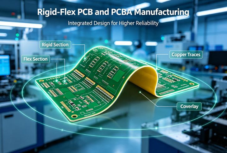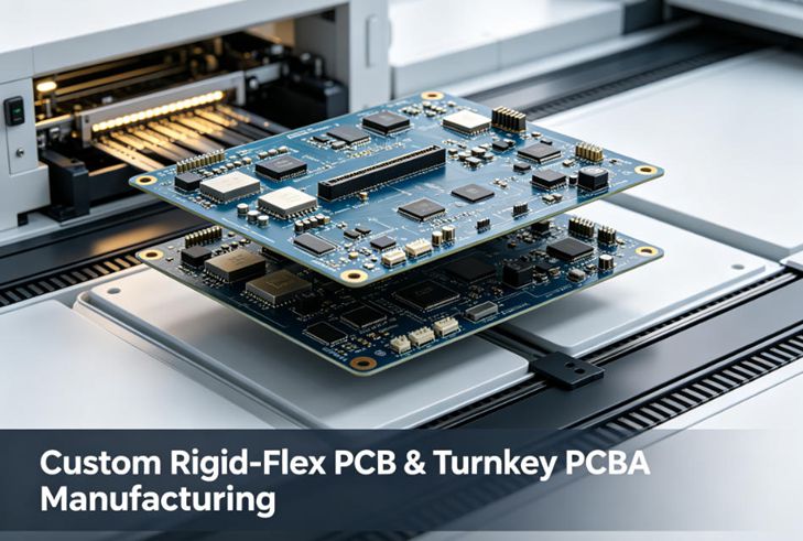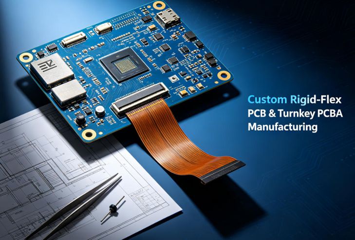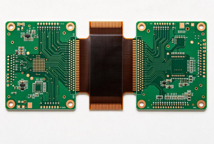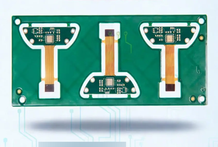
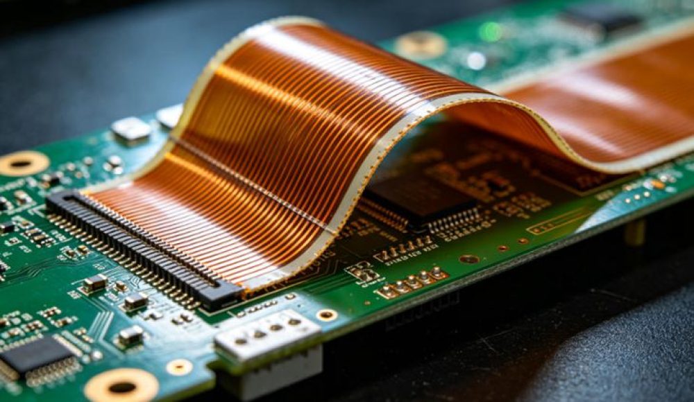
Custom rigid-flex PCB and PCBA manufacturing differs drastically from standard rigid circuit board production, as it combines rigid FR-4 substrates and flexible PI films into one integrated structure. Every design detail directly impacts bending lifespan, assembly yield, long-term reliability and mass production consistency. Latest 2026 industry survey data shows 61% of electronic OEMs encountered costly rework or batch scrap due to overlooked engineering flaws in custom rigid-flex PCB layouts, while 45% delayed product launch cycles by over one month because of unoptimized rigid-flex transition zones.
Design engineers and procurement teams always raise the same core questions when sourcing custom rigid-flex PCB and PCBA services: How to balance bending performance with circuit density? What stack-up rules guarantee stable scalable production? How to avoid hidden solder and lamination defects during PCBA assembly? This blog covers key engineering considerations for custom rigid-flex PCB and PCBA manufacturing, sorts out common customer pain points, and shares standardized engineering solutions from RingPCB’s years of mass production experience for medical, wearable, industrial IoT and aerospace electronics.
1. Stack-Up Engineering: The Foundation of Qualified Custom Rigid-Flex PCB
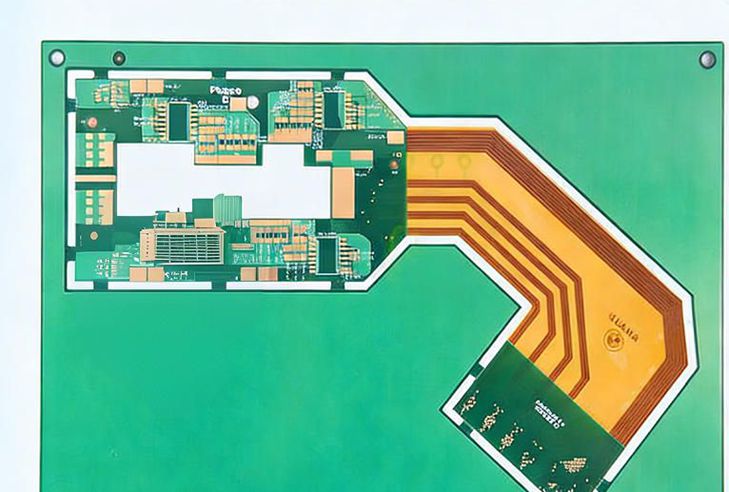
Stack-up design is the most critical engineering link for all custom rigid-flex PCB projects, determining thermal expansion matching, bending resistance and interlayer bonding strength. Many designers copy generic rigid PCB layer structures directly, which triggers irreversible quality risks in custom rigid-flex PCB and PCBA manufacturing.
Industry test data indicates mismatched Z-axis CTE between FR-4 and PI materials causes 39% of rigid-flex delamination failures after thermal cycling. Professional engineering teams must customize asymmetric or symmetric stack-up schemes based on actual bending frequency:
- Low-bending scenarios (≤500 cycles): Simple 2–4 layer custom rigid-flex PCB with single-sided flexible segments
- High dynamic bending (≥10,000 cycles for wearables): Multi-layer balanced stack-up with reinforced adhesive films and thinner copper traces in flex zones
At RingPCB, our engineering team locks stack-up parameters in the DFM phase for every custom rigid-flex PCB order. We automatically mark unreasonable layer ratios, excessive copper weight in bending areas and unprotected transition boundaries, and deliver revised stack-up drawings before prototype production to eliminate early engineering defects. Without standardized stack-up engineering, even perfect Gerber files will lead to unstable PCBA assembly and short service life of finished rigid-flex assemblies.
2. Bending Zone Layout Engineering to Prevent Circuit Breakage
Unreasonable routing inside flex regions is the top complaint from clients purchasing custom rigid-flex PCB and PCBA manufacturing services. 54% of failed prototype tests stem from sharp right-angle traces, heavy copper blocks and insufficient bend clearance inside flexible sections.
Core engineering rules we enforce for all custom rigid-flex PCB:
- All signal traces inside bending zones adopt curved arc routing without sharp corners
- Copper area density is reduced by 40% in flex segments to release bending stress
- Maintain minimum 3mm isolation gap between rigid-flex transition lines and mounting holes
- Reserve neutral axis alignment in stack-up to balance tensile and compressive stress during folding
Our internal reliability lab simulates 100,000 repeated bending cycles for each custom rigid-flex PCB prototype. If trace fracture or microcracks appear after testing, engineers will revise layout schemes free of charge before mass PCBA processing, avoiding huge losses after large-batch production.
3. Material Selection Engineering for Different Application Scenarios
Material matching directly decides the durability of custom rigid-flex PCB and finished PCBA products, and clients often struggle to select suitable PI films, adhesives and coverlays without professional engineering guidance.
- High-temperature industrial equipment: Polyimide with 200°C heat resistance, low-flow adhesive to resist thermal aging
- Medical wearable devices: RoHS-compliant ultra-thin PI with biocompatible coverlay, low-impedance thin copper for precise signal transmission
- Aerospace portable modules: High-Tg reinforced FR-4 rigid sections and anti-oxidation copper foil to withstand harsh temperature fluctuations
Many generic PCB factories use low-cost standard PI materials for all custom rigid-flex PCB orders to cut costs, which leads to bubbling, yellowing or cracking within 1–2 years of field operation. RingPCB’s engineering department provides material comparison reports for every customer project, listing service life, temperature tolerance and total cost of ownership for each material grade, helping clients make cost-effective engineering decisions without blind budget cuts.
4. DFM Engineering Optimization for Smooth PCBA Assembly
Most customers only focus on circuit functionality while ignoring assembly feasibility during custom rigid-flex PCB design, resulting in low SMT yield and extra fixture development costs in PCBA processing. Rigid-flex boards cannot be fixed on standard SMT carriers, so targeted DFM engineering adjustments are mandatory.
Key assembly-focused engineering considerations for custom rigid-flex PCB and PCBA manufacturing:
- Add standardized tooling strips on rigid areas for stable fixture positioning during reflow soldering
- Place all heavy components and large ICs completely outside flexible bending zones
- Control overall board warpage within 0.7% to avoid component offset during printing
- Reserve sufficient clearance for automated AOI and X-ray inspection after assembly
Our engineering team integrates assembly simulation into the DFM review flow of every custom rigid-flex PCB. We pre-judge risks like flex segment sagging, solder paste bridging and component tombstoning, and modify layout outlines or pad sizes at no extra design fee. This one-step engineering optimization boosts PCBA mass production yield above 98.5% for all rigid-flex batches.
5. Reliability Testing Engineering to Verify Long-Term Performance
Customers launching high-volume custom rigid-flex PCB and PCBA products worry most about consistent quality across thousands of units, which is why standardized reliability testing engineering cannot be skipped. Industry data shows manufacturers without dedicated rigid-flex test labs have a 3.2x higher batch defect rate than professional suppliers.
Mandatory engineering test items for all our custom rigid-flex PCB projects:
- Thermal cycling test: -40℃ to 125℃, 1000 cycles to verify lamination bonding
- Dynamic bending endurance test: Up to 100,000 folding cycles
- 85℃/85%RH damp heat aging test for anti-corrosion verification
- X-ray internal inspection after PCBA soldering to check hidden voids and cold joints
Every test generates complete traceable reports attached to shipments, satisfying strict audit requirements for medical, automotive and industrial clients purchasing custom rigid-flex PCB and PCBA manufacturing solutions.
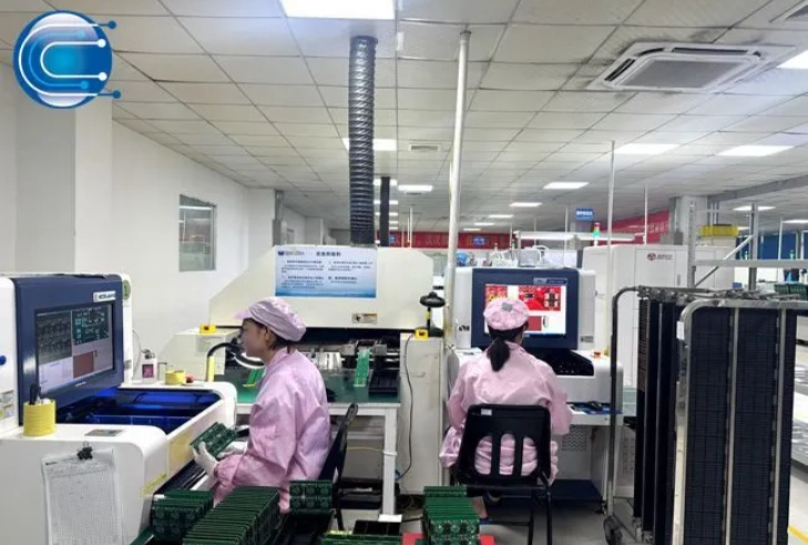
6. Mass Production Engineering Consistency Control
A common customer pain point is inconsistent performance between custom rigid-flex PCB prototypes and mass-produced batches, caused by unstable process parameters without unified engineering standards. Small factories adopt manual semi-custom processes for samples but simplify lamination, exposure and surface treatment for mass orders, creating obvious performance gaps.
RingPCB unifies all engineering parameters for prototype and volume production of custom rigid-flex PCB: fixed material batches, segmented temperature-pressure lamination curves, identical exposure energy and surface finish procedures. Our engineering management system records all production parameters for each project, ensuring every batch of custom rigid-flex PCB and PCBA assemblies matches prototype performance precisely, eliminating post-launch after-sales risks for electronic brands.
Conclusion
Successful custom rigid-flex PCB and PCBA manufacturing relies on systematic engineering control covering stack-up layout, bending zone design, material matching, DFM assembly optimization, reliability testing and batch process consistency. Ignoring any engineering consideration will trigger delayed schedules, high scrap rates and shortened equipment service life.
If you are designing custom rigid-flex PCB and need professional engineering DFM review, stack-up optimization or reliability test scheme consultation, RingPCB’s specialized rigid-flex engineering team offers free technical analysis. Submit your Gerber files and application requirements to rfq@ringpcb.com to obtain customized engineering solutions suitable for prototype verification and scalable mass production.
Visit https://www.ringpcb.com to view more engineering cases of custom rigid-flex PCB and finished PCBA assemblies.