Radar systems are essential for automotive safety (ADAS), industrial monitoring, defense, and advanced 5G/6G telecommunication applications. Designing communication PCBs for radar requires careful attention to high-frequency RF signals, multilayer layouts, and environmental stress factors.
Even small errors in material selection, trace routing, or SMT assembly can reduce radar detection range, degrade signal integrity, or create costly production delays.
In this guide, we highlight 6 common design challenges in radar communication PCBs and explain how Ring PCB’s turnkey services help engineers and OEMs overcome them—from rapid prototyping to mass production.
Challenge 1: High-Frequency Signal Integrity
Radar systems operating at mmWave frequencies (24, 60, 77, 79 GHz) are highly sensitive to signal loss caused by trace impedance mismatch or high insertion loss.
Engineering Solutions:
- Use low-loss PCB materials such as Rogers RO3003, RO4350B, or Isola 370HR.
- Apply controlled impedance routing (50 Ω or 100 Ω) using coplanar waveguides or microstrip traces.
- Optimize copper foil surface roughness to reduce skin effect losses.
Ring PCB Approach:
Our facility leverages precise multilayer stack-up engineering and Time-Domain Reflectometry (TDR) testing to maintain impedance tolerance within ±5%, ensuring optimal high-frequency signal integrity.
Challenge 2: Electromagnetic Interference (EMI) and Crosstalk
High-density radar boards often have digital lines near sensitive RF circuits, causing EMI and phase noise that disrupt radar detection.
Engineering Solutions:
- Isolate analog and digital grounds; implement RF shielding.
- Stitch vias along high-speed traces to prevent near-field crosstalk.
- Route sensitive Tx/Rx lines as differential pairs to cancel common-mode noise.
Ring PCB Approach:
Our engineers conduct rigorous DFM and EMI layout reviews before fabrication, ensuring proper inner-layer shielding and via placement to reduce interference.
Challenge 3: Complex Component Placement & Antenna Routing
Radar PCBs integrate microstrip antennas, MMICs, and high-speed DSPs. Misaligned placement or long routing paths can cause signal reflection and phase distortion.
Engineering Solutions:
- Minimize RF path length between MMICs and antennas.
- Use symmetrical feedlines for multi-channel Rx/Tx arrays.
- Avoid 90° bends; prefer 45° or curved traces for impedance continuity.
Ring PCB Approach:
Our SMT layout engineers ensure precise alignment of BGAs and RF ICs with antenna elements, minimizing parasitic capacitance and phase errors.
Challenge 4: Environmental Durability & Thermal Management
Automotive and industrial radar sensors face thermal cycling, vibrations, and moisture, which can lead to delamination or solder joint fatigue.
Engineering Solutions:
- Use ENIG or Immersion Silver finishes for planar pads and oxidation resistance.
- Embed thermal vias beneath power-dissipating chips.
- Combine RF-optimized materials (Rogers) with FR4 inner layers for mechanical stability.
Ring PCB Approach:
Operating under IATF16949, ISO9001, and ISO14001, Ring PCB ensures reliable material adhesion and solder joint durability for harsh environments.
Challenge 5: Precision SMT Assembly
Ultra-fine pitch BGAs and 0201/01005 passive components make placement critical; even minor misalignment can shift antenna center frequencies.
Engineering Solutions:
- Laser Direct Imaging (LDI) for ±10 μm trace/space tolerances.
- Automated Solder Paste Inspection (SPI) to control solder volume.
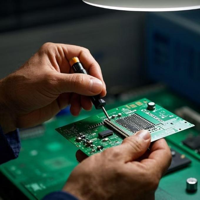
Ring PCB Approach:
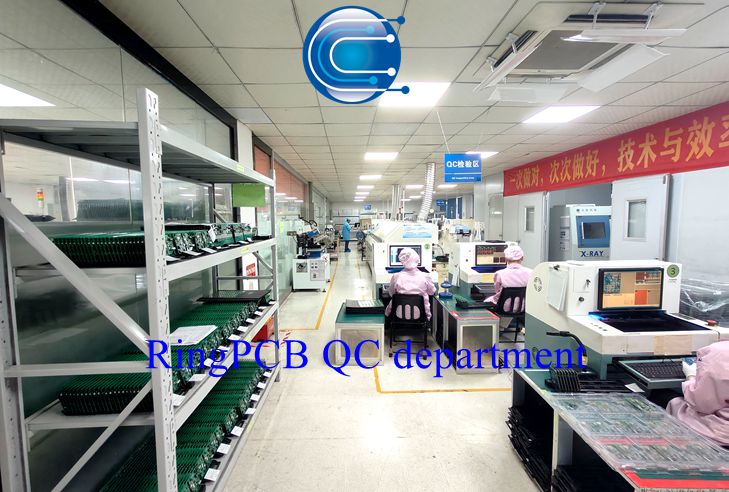
Our turnkey assembly lines feature high-precision Yamaha SMT, inline 3D AOI, X-ray inspection, and ICT testing for 100% component alignment and traceability.
Challenge 6: Rapid Prototyping & Compressed Time-to-Market
ADAS and telecommunication applications demand fast prototyping to validate RF firmware before mass production.
Engineering Solutions:
- Seamless DFM integration for concurrent engineering.
- Agile component sourcing from verified global OCM networks.
Ring PCB Approach:
We provide 3-day rapid prototyping and 7-day mass production runs, with consistent, certified quality control and traceability.
Conclusion
Designing high-frequency radar communication PCBs requires addressing signal integrity, EMI, SMT precision, environmental reliability, and rapid production.
Ring PCB delivers custom turnkey Radar PCBA solutions combining PCB fabrication, global component sourcing, high-precision SMT assembly, and comprehensive testing. OEMs and EMS providers worldwide rely on our 18 years of experience to achieve cost-effective, high-stability radar hardware, from prototype to mass production.