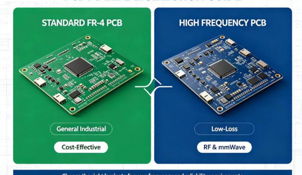
Many hardware teams waste budget by using the wrong PCB material. Some engineers use FR-4 for high-frequency RF circuits and encounter serious signal loss. Others over-spec expensive PTFE boards for low-speed control circuits, raising unnecessary project cost. Understanding the difference between high frequency PCB and standard PCB helps balance performance, reliability and budget.
Core Performance Difference
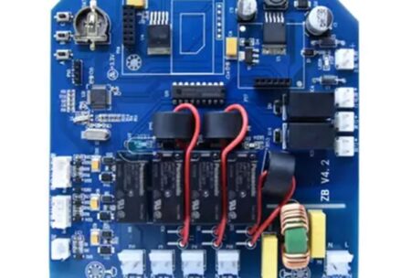
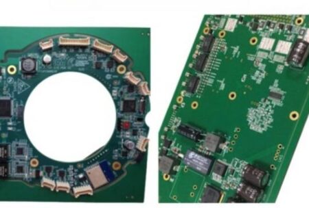
Standard FR-4 PCB works well for low-speed digital and power circuits. It offers affordable pricing and mature manufacturing processes, widely used in industrial control, consumer electronics and power supply boards. But its dielectric constant varies greatly with temperature and frequency. When frequency exceeds 1GHz, signal loss increases rapidly.
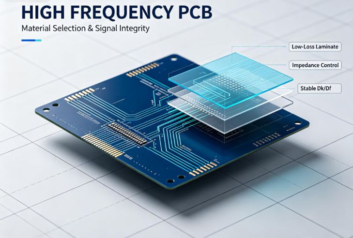
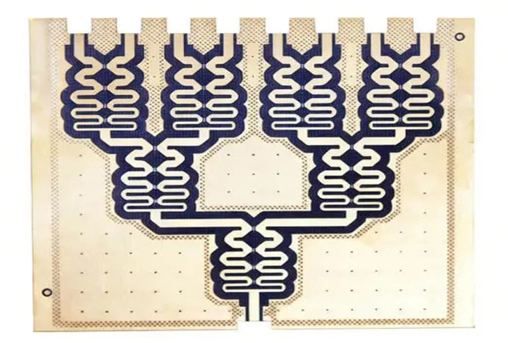
High frequency PCB uses low-loss laminates with stable Dk and Df. The material keeps consistent electrical properties at high frequency, minimizing signal attenuation and phase shift. It is designed for RF, microwave, mmWave radar, 5G antenna and satellite communication hardware.
Application Boundary: Which Board Fits Your Product
Standard FR4 is suitable for industrial control PCBA, low-speed sensor boards, power modules and general embedded hardware. High frequency PCB is required when working frequency is higher than 1GHz, or the system needs high signal integrity for wireless transmission.
For automotive ADAS 77GHz radar and mmWave communication modules, ultra-low-loss materials like PTFE are required. For 5G macro antennas and 2.4GHz/5.8GHz wireless modules, Rogers hydrocarbon laminates are a balanced option.
Cost & Lead Time Trade-offs
There is a clear price gap. High-frequency laminates cost much more than FR4, and the fabrication process needs tighter controls, which extends production time. Hybrid stackup provides a middle solution, applying premium material only for RF signal layers while using FR4 for other layers. This method cuts cost significantly without sacrificing RF performance.
For prototype phase, many engineers prefer small-batch high frequency PCB fabrication to validate RF performance before full mass production. However, not all PCB manufacturers can handle specialized high-frequency materials, so vendor qualification is essential.
Practical Tips for Vendor Selection
When sourcing high frequency PCB, confirm if the factory has experience with your target laminate, impedance control capability and relevant IPC qualification. Ask for previous test reports on insertion loss and dielectric property validation. Avoid vendors who only produce ordinary FR4 boards.
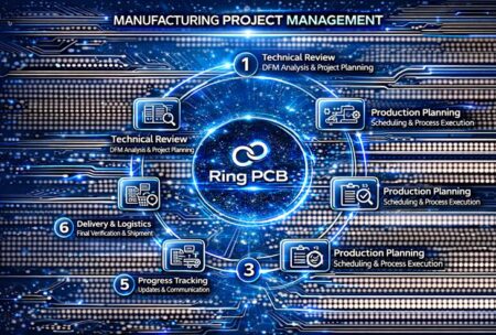
Ring PCB provides both standard PCB manufacturing and high frequency PCB fabrication. Our team can help you evaluate whether your project requires low-loss laminates and recommend suitable stackup options to balance performance and budget. We offer prototype and mass production with full electrical testing for RF and wireless electronics.
Discuss your hardware project requirements with our team, email your Gerber and specs to rfq@ringpcb.com.