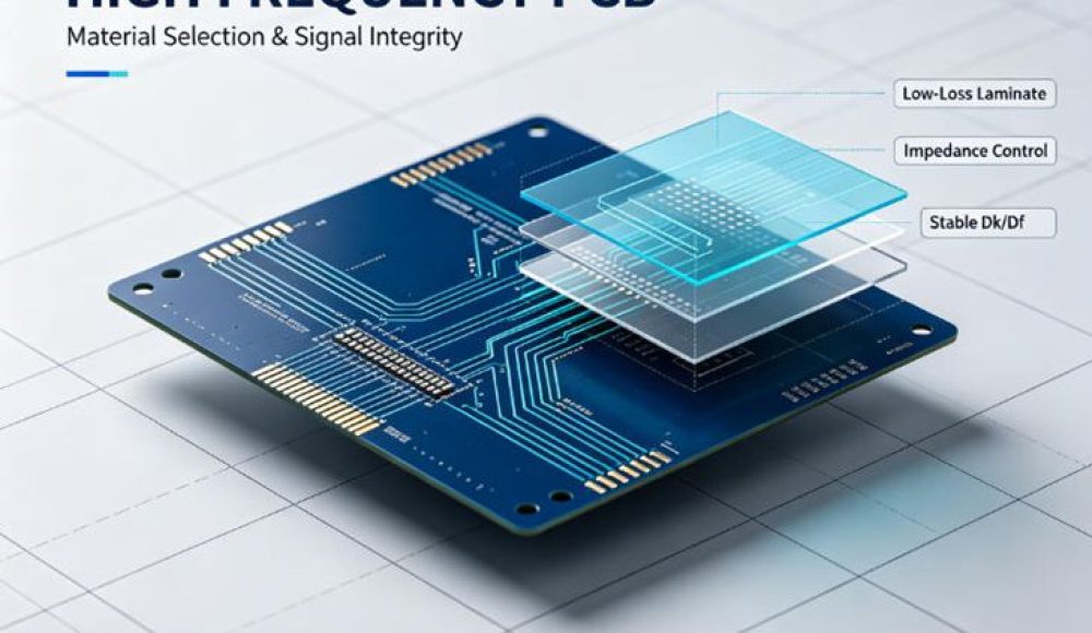
The global high frequency PCB market keeps expanding as 5G base stations, automotive mmWave radar and satellite communication projects accelerate. Industry data forecasts the market will reach over USD 5.2 billion in 2026, driven by growing demand for low-loss signal transmission in high-frequency electronics. Many hardware engineers and procurement teams struggle with one core issue: standard FR-4 laminates fail to maintain stable electrical performance at microwave bands. Therefore, proper material selection is the foundation of reliable high frequency PCB performance.
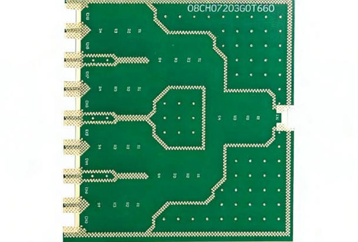
What Makes High Frequency PCB Different from Standard PCB
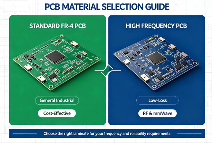
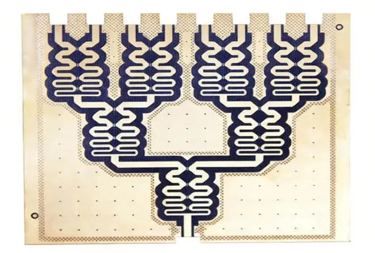
High frequency PCBs are designed for circuits working above 1GHz. Unlike ordinary PCBs, their core requirement is controlling signal attenuation and dielectric constant stability. FR-4 materials show obvious dielectric loss when frequency rises, which causes signal distortion and reduces system stability.
On the contrary, specialized high-frequency laminates such as Rogers RO4000 series, Taconic and PTFE composites maintain steady Dk and low Df across wide temperature and frequency ranges. These materials minimize signal insertion loss, making them ideal for radar, antenna and wireless communication hardware.
Common Material Options & How to Pick Them
First, Rogers hydrocarbon laminates are the most widely adopted option for mid-range RF products. They balance low signal loss and processing cost, suitable for 2–24GHz applications like 5G antennas. Second, PTFE materials deliver ultra-low loss for millimeter-wave systems at 24GHz to 77GHz, often used in automotive ADAS radar and aerospace RF modules.
Hybrid stackup is a cost-effective compromise widely used in current projects. Engineers combine premium high-frequency material on critical RF signal layers with FR-4 for power and control layers. This method cuts total board cost without sacrificing RF performance.
Key Manufacturing Factors Affecting Signal Integrity
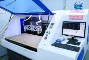
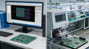
Even with premium laminates, poor fabrication precision can ruin high frequency PCB performance. Impedance control is the top priority. Trace width, copper thickness and laminate thickness must be tightly controlled within tolerance. Minor deviations will shift impedance and create signal reflection.
In addition, surface treatment matters a lot. Immersion gold and HASL options affect insertion loss differently. Moisture absorption must also be limited, as absorbed water will change dielectric parameters and cause unstable performance in outdoor equipment.
Supply Chain Challenges for High Frequency PCB in 2026
In 2026, the supply of specialty high-frequency laminates remains tight, and raw material price fluctuation extends lead times for complex RF boards. Many buyers face delayed delivery or unstable quality from inexperienced manufacturers. It is risky to select general PCB factories without high-frequency process qualification.
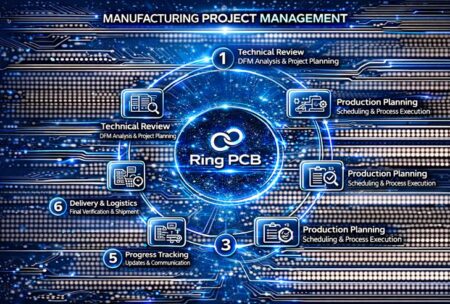
Ring PCB supports high frequency PCB fabrication for RF, radar and telecommunication projects. We handle Rogers, Taconic and hybrid stackup boards with strict IPC quality standards, precise impedance control and full electrical testing. Our engineering team reviews stackup and manufacturing feasibility before production, helping clients reduce prototype iteration cycles and avoid signal integrity failures.
If you have high frequency PCB projects for prototype or mass production, send your specifications to rfq@ringpcb.com for a technical review and quotation.