
As electronic products become smaller and more mechanically complex, engineers are increasingly looking for ways to reduce internal connections while making better use of limited installation space. A conventional rigid PCB works well when the board can be mounted on a fixed surface. A flexible PCB can route circuits through curved or moving spaces. However, some applications need both structural support and flexible interconnection within the same assembly.
This is where rigid flex PCB technology becomes valuable. By combining rigid and flexible circuit sections into one integrated board, rigid-flex construction can help reduce separate cables, connectors, and board-to-board connections. It is used in applications where space, weight, reliability, and mechanical integration are important.
For OEMs, however, rigid-flex is not automatically the best solution. Its advantages must be weighed against design complexity, manufacturing requirements, testing needs, and total project cost.
1. What Is a Rigid Flex PCB?
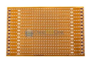
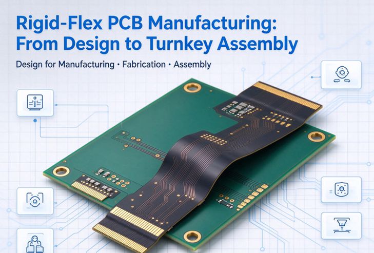
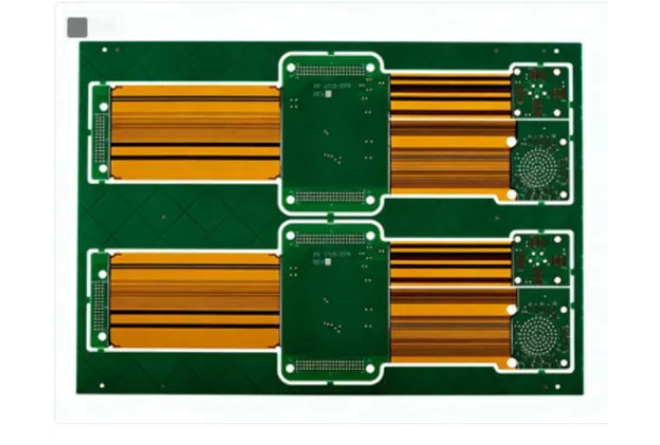
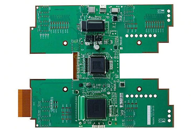
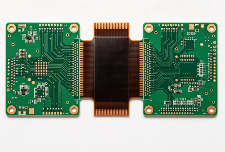
A rigid-flex PCB combines rigid circuit board sections with flexible circuit layers in a single integrated construction. The rigid areas provide stable platforms for mounting components, while the flexible sections allow electrical connections to pass between different board areas or fit into non-flat product geometries.
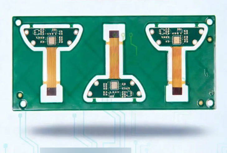
Unlike an assembly made from separate rigid boards connected by cables, a rigid-flex board integrates these functions into one manufactured structure.
A typical application may use rigid sections to support connectors and electronic components, with a flexible section connecting the different areas. Depending on the product, the flexible part may be bent during installation and remain in position, or it may need to withstand repeated movement.
Rigid-flex boards can be designed with different layer structures, material combinations, and transition arrangements. The exact construction depends on electrical performance, mechanical constraints, component placement, and manufacturing capability.
2. Why Are More OEMs Considering Rigid-Flex Technology?
Several product trends are encouraging the adoption of rigid-flex circuits.
First, miniaturization is reducing the space available for conventional cables and connectors. As products become thinner and more compact, separate interconnection components can occupy valuable internal volume.
Second, electronic systems are becoming more integrated. Automotive electronics, medical equipment, aerospace systems, telecommunications devices, and compact industrial products may require multiple circuit areas to operate within a constrained mechanical structure.
Third, reliability expectations are increasing. Every separate connector or cable interface introduces another component and connection point that must be assembled and maintained. Integrating interconnections into a rigid-flex structure can reduce the number of separate interfaces in suitable applications.
Market forecasts reflect the growing commercial interest. Mordor Intelligence estimates that the global rigid-flex PCB market will reach approximately USD 9.48 billion in 2026 and USD 12.74 billion by 2031, representing a projected CAGR of 6.09%. The report identifies applications including foldable consumer devices, automotive electronics, telecommunications, and aerospace and defense. These figures are third-party estimates based on the research firm’s methodology, rather than a universally audited industry total.
For OEMs, the important question is not simply whether the market is growing. It is whether rigid-flex can solve a specific product-level engineering problem more effectively than alternative interconnection methods.
3. Rigid-Flex PCB vs. Separate Rigid Boards and Cables
A rigid-flex design may offer several advantages over an assembly made from multiple rigid PCBs and separate cables.
Reduced interconnection components: Integrating circuit connections can reduce the need for some cable assemblies, connectors, and board-to-board interfaces.
More efficient use of space: Flexible sections can route through areas that are difficult to accommodate with flat rigid boards.
Potential weight reduction: Removing selected cables, connectors, and mechanical supports may reduce the total assembly weight.
Simplified assembly: A well-designed integrated circuit structure may reduce the number of separate interconnection steps during product assembly.
Improved mechanical integration: Rigid and flexible areas can be arranged to match the product’s internal geometry.
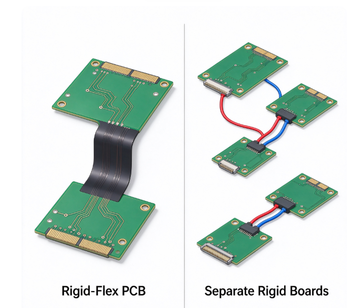
Nevertheless, these benefits are application-dependent. A rigid-flex board may require more specialized materials, more complex manufacturing processes, and higher initial engineering or tooling costs. If a product has sufficient internal space and only a few simple electrical connections, separate rigid boards and cables may remain the more economical option.
The correct comparison should consider the complete assembly rather than the PCB quotation alone.
4. Define the Mechanical Requirements Before Finalizing the Structure
Mechanical requirements are among the most important factors in rigid-flex projects.
The rigid sections must provide adequate support for components, connectors, and mounting features. Meanwhile, the flexible sections must meet the required bending conditions without exceeding their material and structural limits.
Buyers and engineering teams should clarify whether the flexible region is intended for one-time installation bending or repeated dynamic movement. These two conditions involve different reliability considerations.
Important information includes:
- Minimum bend radius
- Bend direction and bend angle
- Static or dynamic bending conditions
- Expected number of movement cycles, where applicable
- Available installation space
- Mechanical support and mounting constraints
- Operating temperature and environmental conditions
The transition between rigid and flexible areas also deserves particular attention. Abrupt mechanical transitions, unsuitable copper arrangements, or insufficiently defined bend areas can create stress concentrations.
For this reason, the mechanical layout and layer construction should be evaluated together. Treating the flexible region as an ordinary extension of a rigid PCB can lead to problems that only become visible during assembly or product operation.
5. Material Selection and Layer Stackup Need Careful Coordination
Rigid-flex PCBs use a combination of rigid and flexible materials. Polyimide is commonly used in flexible sections, while rigid sections may use suitable rigid laminates such as FR-4, depending on the application and construction.
The materials must work together within the complete stackup. Their thickness, thermal behavior, mechanical properties, and bonding characteristics can influence manufacturing and finished-board performance.
Layer arrangement is another important consideration. A rigid-flex design may require different layer configurations in different areas. The manufacturer must understand how the rigid and flexible sections are connected and how the transition is constructed.
Copper distribution, coverlay, adhesive systems, and reinforcement details can also affect the finished board. For higher-density designs, electrical requirements such as controlled impedance and signal integrity may add further constraints.
Before approving the stackup, buyers should confirm that the proposed materials and layer structure are compatible with the required electrical and mechanical performance. Any material substitution should be reviewed and approved against the project’s specifications.
6. Understand the Manufacturing Challenges
Rigid-flex manufacturing combines processes associated with both rigid and flexible circuits. This makes process coordination especially important.
Depending on the board construction, manufacturing may involve inner-layer imaging, etching, lamination, drilling, plating, coverlay application, rigid-section processing, and final contouring. The exact sequence depends on the design and the manufacturer’s process.
Several issues deserve attention.
Layer registration: The different layers and material sections must be aligned according to the specified tolerances. More complex constructions can make registration control more demanding.
Lamination consistency: The rigid and flexible material systems must be combined using an appropriate process. Material compatibility and process conditions influence the finished structure.
Drilling and plating: Hole structures and plated interconnections must be suitable for the selected stackup. Buyers should confirm that the manufacturer’s supported drill sizes and aspect ratios match the project.
Coverlay and opening accuracy: Flexible regions may use coverlay rather than conventional solder mask. Its alignment and openings must meet the requirements of pads and exposed features.
Rigid-to-flex transitions: These areas require careful attention to mechanical layout, material arrangement, and copper geometry.
These manufacturing considerations explain why a supplier’s ability to produce conventional rigid PCBs alone should not be treated as proof of rigid-flex capability. Buyers should specifically confirm the supplier’s rigid-flex process experience and supported construction range.
7. Evaluate Reliability and Inspection Requirements
A rigid-flex PCB should be evaluated as both an electrical circuit and a mechanical structure.
Electrical inspection may include continuity and isolation testing, while dimensional and visual inspection can help verify the finished board against the supplied specifications. Depending on the application, additional reliability evaluations may be needed to assess bending performance, thermal exposure, or other environmental conditions.
The appropriate validation plan depends on the product’s operating environment and expected service life. For example, a circuit bent once during installation does not necessarily need the same bending-cycle validation as a circuit that moves repeatedly during normal operation.
Buyers should define acceptance criteria before production. These may include electrical limits, dimensional tolerances, inspection requirements, and application-specific reliability expectations.
It is also important to confirm which tests are included in the supplier’s quotation and which may require separate arrangements. Clear agreement helps avoid misunderstandings when prototypes are evaluated.
8. How to Control Cost and Project Risk Before Production
Rigid-flex PCBs can have higher unit costs than conventional rigid boards. However, focusing only on board price may lead to an incomplete cost comparison.
A better evaluation considers the total assembly cost, including cables, connectors, assembly labor, mechanical supports, installation time, and potential maintenance requirements.
To control project risk, OEMs should address several points before releasing the manufacturing order:
- Confirm that rigid-flex is necessary for the product’s mechanical and electrical requirements.
- Compare the integrated design with separate rigid boards and cable assemblies.
- Define static or dynamic bending conditions.
- Confirm material selection and the complete layer stackup.
- Review rigid-to-flex transitions and mechanical drawings.
- Agree on electrical inspection and reliability validation requirements.
- Confirm the manufacturer’s actual rigid-flex production capabilities.
- Clarify prototype, tooling, material, and production lead-time assumptions.
Early communication is especially important because rigid-flex manufacturing decisions can affect board construction, mechanical integration, and assembly planning at the same time.
Working with Ring PCB
Rigid-flex projects require manufacturing capabilities that are specific to the combined rigid and flexible construction. Buyers should therefore confirm a supplier’s experience with the exact stackup, material system, bending conditions, and inspection requirements before placing an order.
For conventional rigid PCB fabrication and PCBA projects, Ring PCB provides multilayer PCB manufacturing, component sourcing, SMT assembly, through-hole assembly, and PCBA manufacturing support. Established in 2008, the company operates a self-owned factory covering more than 10,000 square meters, with rigid PCB manufacturing capability of up to 62 layers and five automated SMT production lines.
Ring PCB also uses first article inspection equipment to support production verification. Prototype lead times may be as short as 72 hours, depending on project specifications, material availability, and production conditions.
Customers can provide Gerber files, BOM information, and technical specifications for manufacturing communication and feasibility review. For rigid-flex requirements, the specific construction and manufacturing scope should be confirmed separately before project commitment.
For rigid PCB or PCBA manufacturing inquiries, contact:
References and Sources
- Mordor Intelligence — Rigid-Flex PCB Market Size, Share & 2031 Growth Trends Report, 2026
- Grand View Research — Printed Circuit Board Market Size, Share Report, 2026–2033
- Printed Circuit Engineering Association — Market Watch: AI Computing Surge Reshaping PCB Material Landscape, June 2026
- Ring PCB — PCB and PCBA Manufacturing Trends OEMs Should Watch, September 2026