
As rigid-flex PCBs gain adoption across high-reliability sectors, more hardware buyers discover that the quality gap between different manufacturers can be substantial. Many procurement teams now focus less on price alone, and more on process control and yield consistency. Rigid-flex PCB manufacturing is not just a simple combination of rigid PCB and FPC production. It calls for special handling at nearly every production stage.
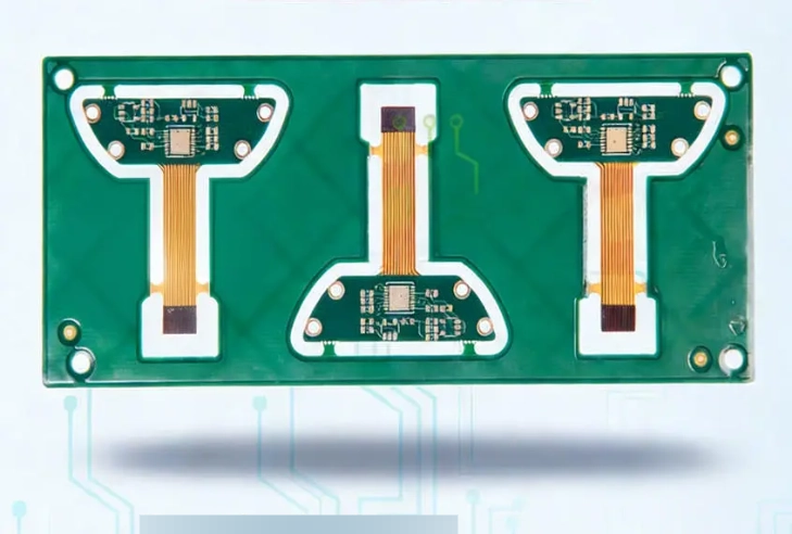
The Unique Fabrication Workflow of Rigid-Flex PCB
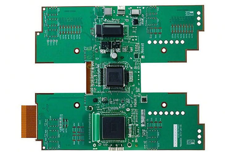
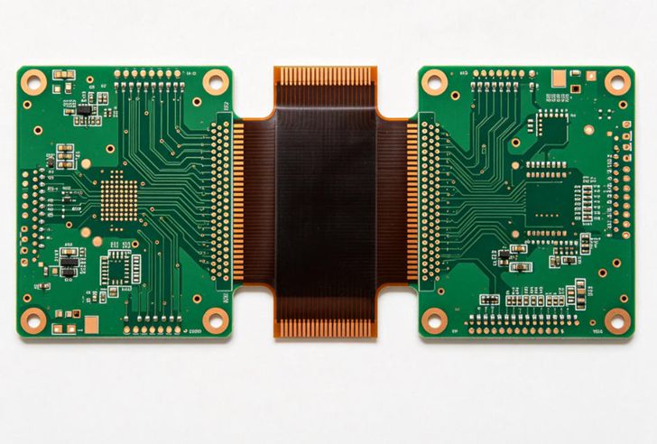
Unlike standard rigid boards, rigid-flex circuits use a hybrid stacking sequence. First, flexible polyimide base films with copper foil are prepared. Then selected areas are laminated with FR-4 rigid reinforcements. After stacking, pressing and curing, the board moves through drilling, plating, patterning, etching and surface finishing. One critical step is protecting the flexible region during lamination. Excess pressure or temperature will damage the polyimide layer or create bubbles between adhesive and copper. Masking films are applied to shield bend zones before pressing. After fabrication, the boards undergo bending endurance testing and impedance verification when high-speed signals are required.
Common Manufacturing Defects to Watch For
Delamination ranks among the most frequent failures. It usually appears at the rigid-flex boundary, triggered by poor material compatibility or improper lamination parameters. Trace cracking in flex areas is another typical issue. It often arises from insufficient bend radius, copper that is too thick, or traces placed right across the folding line. Additionally, misregistration between layers causes broken vias and impedance deviation. For multi-layer rigid-flex boards, layer-to-layer alignment must stay within tight tolerances throughout the whole PCB manufacturing process. Surface finish also affects long-term reliability. Surface treatments such as ENIG or OSP must be applied without damaging the soft flexible substrate.
Quality Testing Standards for Rigid-Flex PCB
Reputable manufacturers follow IPC-6013 specifications for flexible-rigid circuits. Tests usually include thermal cycling, peel strength measurement, dynamic bend testing, continuity and insulation resistance checks. For high-reliability applications, lot sampling records and full material traceability are required. Many customers overlook bend testing at the prototype phase. Static visual inspection cannot detect fatigue failures that only emerge after thousands of folding cycles. Including bend tests in your validation plan helps avoid costly field failures after mass launch.
How DFM Reduces Manufacturing Risks
Design for manufacturability is especially important for rigid-flex PCB. The manufacturer’s engineering team should review the drawing before production. They check bend radius, copper direction, trace width, keep-out zones in flex sections, and stack-up construction. Many expensive redesigns can be avoided through this early review. Some designs push stack complexity beyond standard factory capabilities. An experienced supplier can suggest practical adjustments that preserve product performance while improving yield and shortening lead time.
Finding a reliable supplier that fully understands rigid-flex PCB manufacturing can save OEMs from costly delays and product recalls. Ring PCB’s in-house factory has accumulated rich experience with custom rigid-flex projects. Our QC system implements strict process monitoring at lamination, drilling and final testing stages. We provide DFM feedback at the prototype stage and maintain full batch traceability for industrial and medical-grade rigid-flex orders.
Reach out to discuss your rigid-flex PCB project and request quotation. Email us at rfq@ringpcb.com.