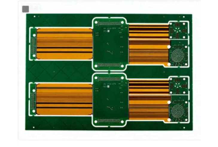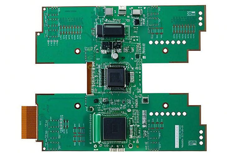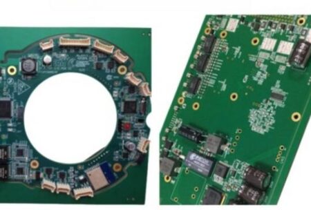

A Rigid-Flex PCB prototype that powers on successfully is not necessarily ready for mass production.
This distinction matters for OEMs.
During early development, engineers may focus primarily on electrical function. However, once a product moves toward NPI and volume manufacturing, additional questions appear: Can the board be manufactured repeatedly? Can it be assembled without damaging flex areas? Is the BOM stable? Are test points accessible? Will mechanical folding remain consistent? Can inspection detect the defects that matter?
For Rigid-Flex PCB projects, answering these questions before mass production can prevent expensive redesigns and production delays.
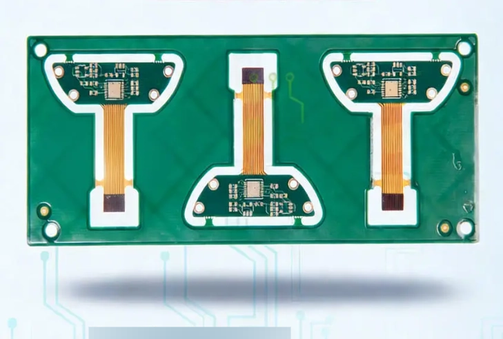
Prototype Success Is Only the First Milestone
Prototype quantities are forgiving in ways that mass production is not.
Engineers can manually inspect individual boards, make small modifications, replace components, or adjust assembly methods during a prototype build.
Those interventions become expensive when quantities increase.
Therefore, NPI should convert a working design into a repeatable manufacturing process.
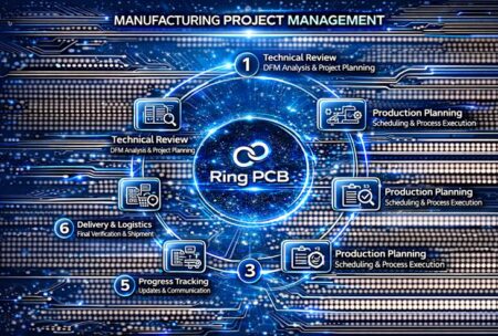
For rigid-flex products, this involves coordinating PCB fabrication, mechanical requirements, component sourcing, PCB assembly, inspection, and testing before volume release.
The earlier these activities are aligned, the easier it becomes to identify risks while they are still inexpensive to correct.
Freeze the Stackup Before Production Planning
Rigid-flex stackup is fundamental to electrical and mechanical performance.
Engineers must define which layers remain rigid, which enter flex areas, what materials are used, how copper is distributed, where coverlay is applied, and how the circuit transitions between rigid and flexible sections.
Changes to the stackup can affect finished thickness, impedance, bend behavior, drilling, lamination, and mechanical fit.
Consequently, the PCB Manufacturer should confirm the proposed stackup before tooling and material preparation.
For controlled-impedance designs, trace geometry, dielectric thickness, copper thickness, and material properties should also be evaluated together.
This is particularly important in high-speed or RF circuits where seemingly small geometry changes can affect electrical performance.
Define Static and Dynamic Flex Requirements
Not every flexible circuit performs the same mechanical job.
Some rigid-flex boards bend only during final product installation. Once installed, they remain in a fixed position. These are generally static flex applications.
Others bend repeatedly during normal product operation. These are dynamic flex applications.
The distinction can influence material selection, copper construction, routing strategy, bend radius, layer count, and mechanical design.
Therefore, the PCB Manufacturer should understand how the product will actually move.
Simply marking an area as “flex” on a drawing does not provide enough information for every application.
Engineers should communicate expected bend angle, bend radius, number of flex cycles where relevant, installation method, and mechanical constraints.
Keep Critical Features Away From Bend Stress
One of the most important rigid-flex design principles is controlling stress.
Vias, plated holes, component pads, and abrupt copper features can create mechanically sensitive areas. Their position relative to the bend zone should therefore be reviewed carefully.
Trace routing also matters.
Curved or appropriately transitioned routing may help distribute mechanical stress better than poorly positioned abrupt geometries. Copper balance and flex-layer construction should also be considered.
Furthermore, mechanical drawings should identify the actual fold direction and final installed shape.
Without this information, the PCB layout may satisfy electrical requirements while creating avoidable mechanical risk.
Panelization Must Consider Both Fabrication and Assembly
Panelization is often treated as a PCB fabrication detail, but it can strongly influence turnkey PCB assembly.
Rigid-flex boards may have irregular shapes or unsupported flexible sections. During solder paste printing and component placement, the assembly needs adequate mechanical stability.
The PCB Manufacturer and PCBA team should therefore coordinate panel rails, tooling holes, fiducials, breakaway structures, and support requirements.
In some cases, dedicated assembly fixtures or carriers may be needed.
Planning this before the first assembly build can improve printing stability, placement accuracy, reflow handling, and inspection consistency.
It can also prevent unnecessary redesign of the production panel after the PCB has already been approved.
Review the BOM Before NPI Release
A manufacturable PCB is not enough if the required components cannot be purchased.
Before NPI, the BOM should be checked for manufacturer part numbers, package compatibility, lifecycle status, availability, lead time, and sourcing risk.
This is particularly important when prototypes were assembled using sample components or inventory that may not be available for production quantities.
Alternative parts should never be substituted without appropriate engineering approval.
However, identifying potential alternatives before a shortage occurs gives procurement and engineering teams more time to evaluate them.
A full-turnkey electronics manufacturing workflow can connect BOM review directly with production planning instead of treating sourcing as a separate activity.
Build the Inspection Strategy Around the Design
Inspection should be selected according to the actual assembly.
SPI can verify solder paste deposition before placement. AOI can identify visible soldering and placement defects. X-ray can inspect hidden joints under packages such as BGA and QFN.
However, inspection alone does not confirm that the product performs correctly.
Depending on the application, flying probe, ICT, programming, functional testing, or customized test fixtures may also be appropriate.
Therefore, DFT should be discussed during NPI.
Test points, programming access, connectors, fixtures, and acceptance criteria should be defined before volume production whenever possible.
Otherwise, a product may be manufacturable but unnecessarily difficult or expensive to test.
Use Pilot Production to Validate the Process
Moving directly from a few prototypes to thousands of assemblies can create avoidable risk.
A pilot build provides an intermediate step.
During pilot production, the manufacturer can verify fabrication yield, assembly fixtures, reflow parameters, component handling, inspection coverage, test procedures, cycle time, and documentation.
Engineering changes discovered at this stage can then be incorporated before larger material commitments are made.
Pilot production is also useful for establishing golden samples, workmanship criteria, test limits, and process records.
For OEMs, this makes the pilot run an important manufacturing validation activity rather than simply a larger prototype order.
Control Engineering Changes After Validation
Once a Rigid-Flex PCB and its assembly process have been validated, changes should be controlled carefully.
A seemingly minor modification to a component footprint, flex length, stackup, via structure, material, or mechanical outline can influence other parts of the process.
Revision control is therefore essential.
Gerber or ODB++ data, BOM revisions, assembly drawings, mechanical files, test procedures, and approved substitutions should all identify the correct product revision.
This becomes increasingly important when several teams or suppliers are involved.
One advantage of turnkey PCB assembly is that PCB fabrication, sourcing, assembly, and testing can operate through a more coordinated change-control process.
Moving From NPI to Stable Production
Successful NPI is ultimately about removing uncertainty before volume production.
The PCB design must be manufacturable. The flex structure must meet mechanical requirements. Components must be available. Assembly tooling must work. Inspection must cover critical defects. Testing must verify the required functions. Documentation must identify the correct revision.
A PCB Manufacturer that also provides turnkey PCB assembly can help connect these requirements instead of treating them as separate activities.
Ring PCB supports Rigid-Flex PCB fabrication, engineering review, component sourcing, SMT and THT assembly, inspection, testing, and full-turnkey electronics manufacturing. Customers can begin with prototypes or small-batch NPI builds and then scale toward volume production as the design and manufacturing process become stable.
If you are preparing a Rigid-Flex PCB for prototype, NPI, or mass production, send your Gerber or ODB++ files, BOM, drawings, expected quantities, and testing requirements to rfq@ringpcb.com for project evaluation.