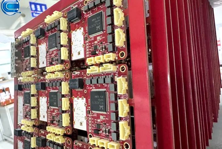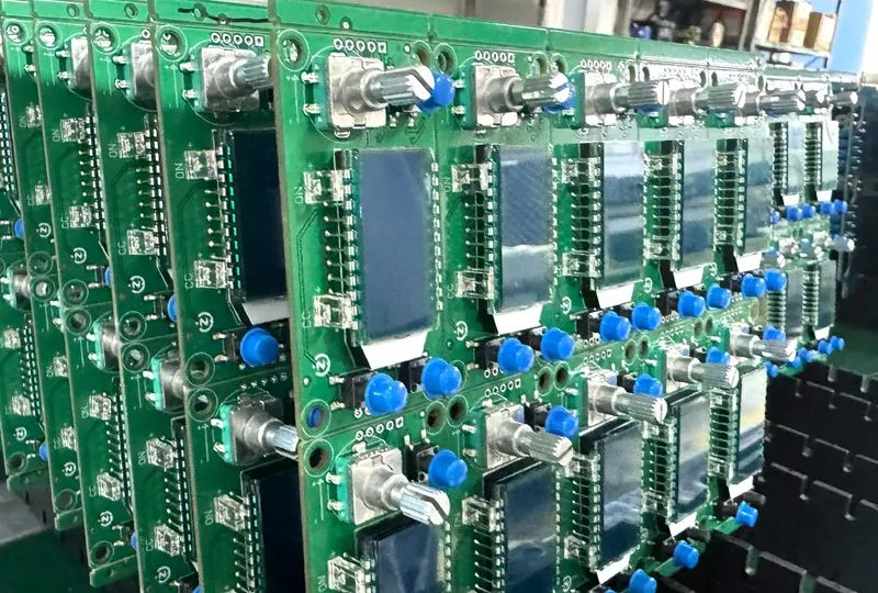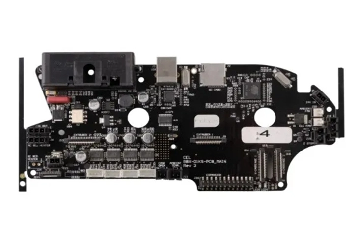
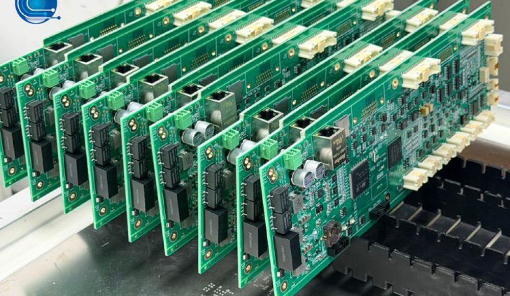
Industrial control electronics are expected to operate consistently in environments that can be considerably more demanding than typical consumer applications. Control boards used in factory automation, motor control systems, robotics and production machinery may experience continuous operation, temperature fluctuations and mechanical vibration.
As industrial facilities adopt more connected equipment and intelligent automation, electronic control systems also become increasingly important to production continuity. A PCBA failure can interrupt machine operation, affect production schedules and create additional maintenance costs.
For industrial OEMs, therefore, evaluating an Industrial Control PCBA manufacturer involves more than checking PCB specifications or assembly prices. Buyers need to understand how the PCB structure, component selection, assembly process and quality controls contribute to long-term reliability.
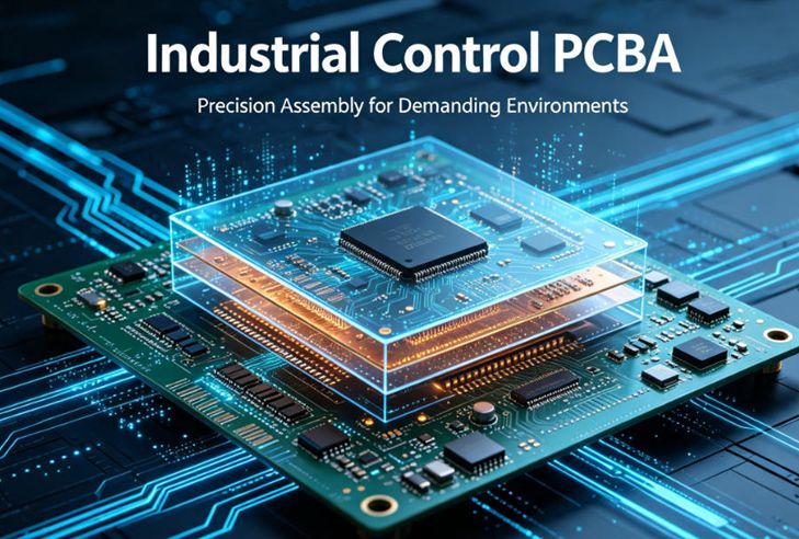
Three factors deserve particular attention: thermal cycling, mechanical vibration and solder joint integrity. These factors are closely related, and weaknesses in one area can increase the risk of failure during actual equipment operation.
2. Thermal Cycling: A Long-Term Challenge for Industrial PCB Assemblies
Industrial control equipment does not always operate at a constant temperature. Power components generate heat during operation, while equipment shutdowns, changing workloads and surrounding environmental conditions can cause repeated temperature fluctuations.
Over time, these temperature changes can place mechanical stress on electronic assemblies.
How Temperature Changes Affect PCBA Reliability
Different materials in an electronic assembly expand and contract at different rates. These include the PCB substrate, copper conductors, solder joints and component packages.
Repeated temperature changes can create cyclic mechanical stress, particularly around solder connections. Under demanding conditions, this may contribute to solder fatigue, cracking or intermittent electrical connections.
The risk depends on several factors:
- The temperature range and frequency of operating cycles
- Differences in thermal expansion between components and PCB materials
- Component package dimensions and construction
- PCB thickness and mechanical characteristics
- Solder joint geometry and assembly quality
For example, a large power component mounted near a high-density control IC may experience a different thermal environment from smaller components elsewhere on the board. Uneven temperature distribution can create additional stress across the assembly.
Why Thermal Design and Assembly Must Work Together
Thermal reliability is not determined by PCB material alone. Component placement, copper distribution, power routing and heat dissipation all influence operating temperatures.
For an industrial control board using Heavy Copper PCB technology, thicker copper may support current-carrying requirements and heat spreading in selected areas. However, it does not eliminate the need for appropriate component thermal management or a validated assembly process.
Similarly, HDI PCB structures can support compact component integration, but higher component density may require closer attention to local heat concentration.
Therefore, OEMs should evaluate PCB construction and PCBA assembly as one manufacturing system rather than treating them as separate purchasing decisions.
3. Mechanical Vibration: Protecting Solder Joints and Component Connections
Industrial equipment often contains moving parts, motors, pumps, fans and mechanical transmission systems. These can generate vibration that is transmitted to electronic control assemblies.
In applications such as industrial robots, machine tools, motor drives and automated production lines, repeated mechanical loading may affect component connections and PCB mounting structures.
Common Vibration-Related Risks
Several areas of an industrial PCBA may require attention:
Large and Heavy Components
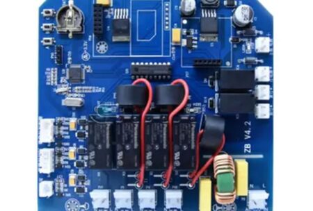
Transformers, capacitors, inductors, relays and large connectors can create localized mechanical loads. If the board experiences repeated vibration, these components may place additional stress on their solder joints.
Board-to-Connector Interfaces
Connectors are particularly important because they provide electrical and mechanical connections between the PCB and external equipment. Cable movement, connector insertion forces and vibration can affect connection stability.
PCB Mounting and Support
The board’s mounting positions and support structure influence how mechanical forces are distributed. Poor support or excessive board flexure can increase stress around components and solder joints.
Practical Manufacturing Considerations
Industrial OEMs should provide the PCBA manufacturer with relevant mechanical information, including board dimensions, mounting-hole locations, connector positions and the approximate mass of large components.
For assemblies exposed to substantial vibration, the engineering review should also consider:
- Component placement in relation to mounting points
- Mechanical support for heavy components
- Connector retention and cable strain relief
- PCB thickness and board support
- Potential stress around solder joints and component pads
These considerations are particularly important for control boards installed close to motors, pumps or other vibration-generating equipment.
4. Solder Joint Reliability: Connecting PCB Fabrication with PCBA Quality
Solder joints provide both electrical connections and mechanical attachment between components and the PCB. Their quality is therefore essential to the reliability of industrial control assemblies.
A visually acceptable solder joint does not automatically guarantee long-term performance under repeated thermal and mechanical stress.
Solder Paste Printing and Reflow Control
Inconsistent solder paste deposition can lead to insufficient solder volume, bridging or uneven joint formation. Reflow conditions also need to be appropriate for the PCB construction and component requirements.
For industrial control PCBA, the assembly process should consider:
- Stencil design and solder paste volume
- Component package and pad geometry
- PCB copper distribution and thermal characteristics
- Reflow temperature profile
- Component moisture sensitivity and handling requirements
For boards combining large power components with fine-pitch control devices, process control is especially important because different component types may respond differently to the same thermal cycle.
Inspection Methods for Different Component Types
No single inspection method can identify every possible assembly defect.
- SPI: Evaluates solder paste volume, position and printing consistency before component placement.
- AOI: Identifies visible defects such as component misalignment, polarity errors and soldering abnormalities.
- X-ray Inspection: Helps inspect hidden solder connections in packages such as BGAs and other components with concealed joints.
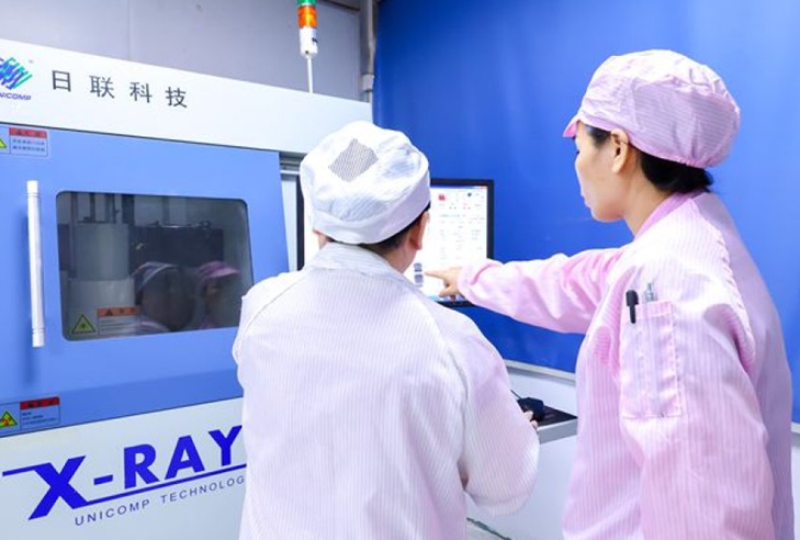
These inspection methods support manufacturing quality control, but they do not replace application-specific reliability testing.
5. Using Reliability Standards to Define Appropriate Testing
Industrial OEMs should establish testing requirements based on the equipment’s actual operating environment. Rather than applying the same test conditions to every PCBA, buyers and manufacturers should agree on relevant environmental conditions, test severity and acceptance criteria.
Several established standards provide useful references.
Temperature Change Testing
IEC 60068-2-14:2023 covers environmental testing methods for evaluating the effects of specified temperature changes on test specimens. It provides a framework for defining temperature-change conditions and reporting test results.
For industrial control assemblies, temperature-change testing may be relevant when equipment experiences repeated heating and cooling during operation or when environmental temperature variation is expected.
Vibration Testing
IEC 60068-2-6 describes a sinusoidal vibration test method used to assess whether components and equipment can withstand specified vibration severities. The method can help identify mechanical weaknesses or performance degradation under defined test conditions. <Cite refs={[“turn929504search7”]}/>
The appropriate vibration profile should reflect the equipment’s installation location, operating conditions and customer requirements.
Thermal Cycling of Solder Attachments
IPC-9701B:2022 establishes a thermal cycling test method for characterizing the fatigue life of surface-mount solder attachments. Its results can support analysis of solder joint reliability under specified use conditions.
It is important to distinguish between manufacturing inspection and reliability qualification. SPI, AOI and X-ray inspect assembly characteristics, while environmental and thermal cycling tests evaluate performance under defined stress conditions.
Not every PCBA project requires every test. The test plan should be agreed upon according to product risk, application requirements and the responsibilities of the OEM and manufacturing supplier.
6. What Industrial OEMs Should Check Before Mass Production
Reliability issues are generally easier to address before mass production than after products have entered the field. A structured manufacturing review can help identify potential risks early.
Before placing a production order, OEMs should consider the following:
- Operating environment: Define expected temperature ranges, vibration conditions, humidity exposure and duty cycles.
- PCB construction: Review board thickness, material, copper distribution, layer structure and mounting requirements.
- Component selection: Check package size, component weight, thermal characteristics and suitability for the intended environment.
- Assembly process: Review solder paste printing, placement accuracy, reflow conditions and any special handling requirements.
- Inspection plan: Determine whether SPI, AOI, X-ray or additional inspection methods are appropriate.
- Reliability testing: Specify environmental tests, sample quantities, test conditions and acceptance criteria when required.
- Production consistency: Confirm that approved manufacturing data, component revisions and process requirements are maintained during production.
For products with different models or configurations, revision control is also important. Changes to component packages, PCB materials or assembly specifications should be reviewed before implementation.
7. Industrial Control PCB and PCBA Manufacturing at Ring PCB
Ring PCB provides PCB fabrication, component sourcing, SMT assembly and through-hole assembly for industrial electronics projects.
Established in 2008, Ring PCB operates a self-owned manufacturing facility covering more than 10,000 square meters. Its PCB and PCBA manufacturing operations support a range of industrial control applications, including projects requiring multilayer, HDI and Heavy Copper PCB constructions.
The company’s manufacturing capabilities include:
- Multilayer PCB fabrication with up to 62 layers
- HDI PCB structures and specialized interconnection processes
- Heavy Copper PCB production for demanding current-carrying applications
- Five automated SMT production lines
- SPI, AOI and X-ray inspection equipment
- PCB fabrication, component sourcing and PCBA assembly services
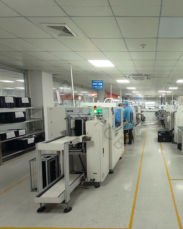
These capabilities allow customers to coordinate PCB manufacturing and assembly requirements through one supplier. Actual process feasibility and inspection scope depend on the project specifications.
Customers can submit Gerber files, BOM information and specific technical requirements for manufacturing communication and feasibility review before order confirmation.
If you are evaluating an Industrial Control PCBA manufacturer for automation equipment, motor control systems or other industrial electronics, contact Ring PCB at rfq@ringpcb.com to discuss your manufacturing requirements.
References
- International Electrotechnical Commission (IEC). IEC 60068-2-14:2023 – Environmental Testing, Part 2-14: Tests – Test N: Change of Temperature.
- International Electrotechnical Commission (IEC). IEC 60068-2-6:2007 – Environmental Testing, Part 2-6: Tests – Test Fc: Vibration (Sinusoidal).
- IPC. (2022). IPC-9701B: Thermal Cycling Test Method for Fatigue Life Characterization of Surface Mount Attachments.
- IPC. IPC-A-610: Acceptability of Electronic Assemblies.